Nest
![]()
Arrange parts on the plate to maximize material utilization. There are 2 different nesting dialogues that can be accessed from the Nest tool: the Shape Nester, and the Block Nester.
Common Nesting Parameters
| Quantity |
The number of copies of the selected parts to create and nest. An individual quantity can be applied to each part by selecting each part and changing the quantity before clicking apply. |
| Priority Order |
The priority for each object to be nested used to determine the nesting order. |
| Gap |
Minimum distance between each contour being nested. |
| Margin |
Minimum distance between the edge of the plate and the contours being nested. |
| Multiple Sheets |
When checked, additional layers will be created to allow for the nesting of all objects. After nesting objects, all layers will be turned on, click the layer arrows to cycle through nested layers. |
| Create Remnant |
When checked, create a contour that represents the remnant of the material used to cut the objects. The remnant can be created and a new plate can be created. See Create Plate from Contour |
| Create Summary |
A summary report will be generated when checked. The report can be accessed by using the View Summary tool |
Shape Nester Dialogue
![]()
Shape Nester Types
Standard
The base nester that has been the standard since EnRoute version 4.
New
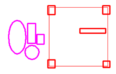
The New nester is capable of recognizing contours within plate boundaries as obstructions and will nest around them providing a simple way to avoid clamps or a section of the material with defects.
Legacy
The original nester in early versions of EnRoute.
Shape Nester Parameters
| Nest Originals |
When checked, the original objects will be nested. When additional quantities are defined, the originals will be highlighted when nested. |
| Step Angle |
Specify the angle in degrees objects are allowed to rotate by when nesting |
| Use Holes |
When checked, smaller contours will be nested inside the holes of larger contours |
| Obstruct (New Nester Only) |
When checked, contours within the boundaries of the plate will be recognized as obstructions. Contours will be nested around obstructions. Obstructions must be selected with the contours to be nested before activating the Nest tool. Obstruction contours will be displayed in red.
|
| Reference Grid |
Click the position of the plate to nest the contours in. The New nester allows multiple locations to be selected. |
Block Nester Dialogue
![]()
Designed to nest squares and rectangles efficiently and provide tools to align contours for optimized cutting.
Block Nester Parameters
Allow Rotate |
When checked, selected contours can be rotated when nested. |
Create Common Line |
When checked, the block nester will generate a common line contour that can be used to generate toolpaths. The common line contour prevents double cutting rectangular parts. See the example below. |
Common Line Example
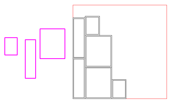
Using the block nester, the parts pictured below were nested and the common line was created using the following parameters:
| Quantity | 2 |
| Gap | 0.25" |
| Margin | 0.25" |
| Create Common Line | Checked |

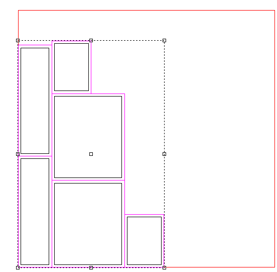
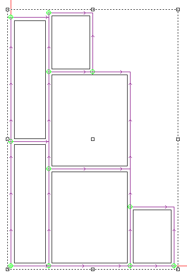
To cut the parts, a toolpath must be generated from the common line contour. Select the common line contour.

Activate the Open Contour Offset tool ![]() . Select a 1/4" end mill tool, and from the strategy parameters section, select the follow Middle of contour option. Click OK to apply the toolpaths.
. Select a 1/4" end mill tool, and from the strategy parameters section, select the follow Middle of contour option. Click OK to apply the toolpaths.

By assigning the gap distance the same with as the tool, both sides of adjacent parts can be cut at the same time.

